| Low Noise Amplifier : Circuit, Working, Types & Its Applications | 您所在的位置:网站首页 › chiq gain low › Low Noise Amplifier : Circuit, Working, Types & Its Applications |
Low Noise Amplifier : Circuit, Working, Types & Its Applications
|
What is Low Noise Amplifier : Working, Types, Design & Its Applications
June 10, 2022 By WatElectronics In a communication system, a low noise amplifier or LNA is an essential component in the receiver section. The main role of this amplifier is to amplify the weak signal by keeping the noise as small as possible. The performance of this amplifier can be measured most particularly by considering different factors like its noise figure, gain, dynamic range, matching, stability, and return loss. These amplifiers play a key role in millimeter-wave applications like passive remote sensing, Earth science radiometry, transceivers, and radio astronomy. This article provides brief information on Low noise amplifiers which are also called LNAs. What is a Low Noise Amplifier?A low noise amplifier definition is an electronic amplifier that is capable of amplifying very weak signals & provides voltage levels appropriate for A/D conversion otherwise further analog processing. These amplifiers are used in applications where low amplitude sources involve transducers & antennae. 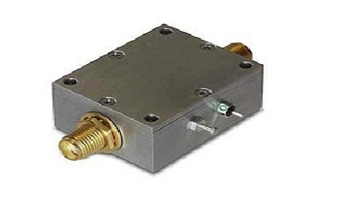 聽Low Noise Amplifier The working principle of a low noise amplifier is to amplify a low-power signal without degrading its S/N ratio. Generally, normal amplifiers amplify signals but they introduce additional noise to the system. So, LNA is used to reduce the noise. These amplifiers are found in electronic test equipment, medical instruments, and radio communications systems. SpecificationsThe specifications of the low noise amplifier are discussed below. GainThe gain of an LNA is the ability to amplify or increase the input signal level at a level that can be processed by the receiver. The gain is specified in dB and the typical gain values of LNA range from 10 to 30 dB. Noise FigureThe noise figure can be defined as the ratio of whole output noise power and the output noise because of the input source. The noise figure signifies the quality of amplifiers. The noise figure specifies the noise performance of an RF system and it is generally measured by using typical signal generators or noise generators. When the noise figure value is low then the RF system performance will be better. Generally, the low noise amplifier amplifies both the signal & noise available at its input. Additionally, the output includes noise because of the low noise amplifier. This in turn decreases the S/N ratio. So a good LNA contributes extremely small noise that is A low noise amplifier or LNA is a simple microwave amplifier. A power amplifier or PA is an electronic amplifier. LNA (Low-noise amplifier) is mainly optimized for low input noise, either current noise (In) or voltage noise (Vn). PA (Power amplifier) is mainly optimized for power gain. RF frequency range is 60 to 90 GHz. RF frequency range is 71 to 76 GHz. Noise figure 5dB. Noise figure 10 dB or above. The small-signal gain is 30dB. The small-signal gain is 32dB. Weight is 1.5 oz. Weight is 1.7 oz. Low Noise Amplifier Block Diagram In a communication system, the receiver section needs amplification for the weak signal which is received from the antenna. So this amplification can be accomplished through the main component called Low Noise Amplifier or LNA. The characteristics of this amplifier can be described by certain parameters like gain, noise figure, chip area, linearity, power consumption & bandwidth. The block diagram of the low noise amplifier is shown below. The designing of a low noise amplifier can be done by using a common gate amplifier, active inductor & common drain stage. Generally, the common gate amplifier is mainly used at the input stage whereas the common drain amplifier is used at the output stage to provide the best input as well as output matching. The low noise amplifier is bound with particular characteristics like gain & noise figure but the selection of LNA mainly depends on some specific parameters like power supply, bandwidth, chip area & linearity. 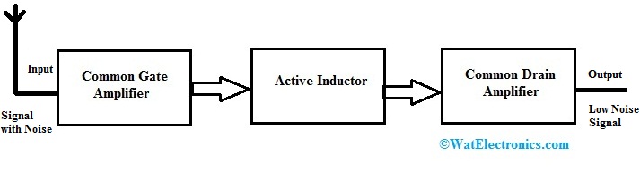 Block Diagram of Low Noise Amplifier Common Gate AmplifierThe common gate (CG) amplifier forms the primary stage of the proposed LNA. By this stage, it is not much complex to get input impedance matching. This amplifier can be used as a current buffer or voltage amplifier. Active InductorAn active inductor mainly includes CMOS transistors & its operation is simply the same as a passive inductor. This inductor is mainly designed to give good quality factors to determine its efficiency. The performance of this inductor can be enhanced by introducing dual feedback while designing the circuit. Common Drain AmplifierGenerally, a common drain amplifier is known as a buffer or a source follower. It is normally used at the output stage of the LNA design. This amplifier has less output impedance. So, it can provide good output impedance matching. The proposed low noise amplifier design can be accomplished in 45nm CMOS technology. The LNA comprises 12 transistors, but using the least number of transistors within the design will be useful for decreasing the power consumption and parasitic effects. In the above three-stage low noise amplifier, the common gate amplifier is used as an input stage. This amplifier is extensively used in wireless communications. First, this common amplifier receives a signal with noise from the antenna. The noise figure is somewhat high in this stage. This noise signal is transmitted to the next stage of the LNA like an active inductor. In an active inductor, the noise of the received signal can be reduced because of noise-canceling & resistive degeneration. An active inductor is used to get low power consumption, reducing complexity. This low noise signal is given to the final stage of LNA like a common drain amplifier. This is also called a buffer or source follower. This amplifier is capable to obtain small output impedance matching. So this amplifier has potentially very less noise. In this way, the noise is reduced from input to output of LNA. Low Noise Amplifier Circuit DiagramThe circuit diagram of a low noise microphone pre-amplifier with NE5534 IC is shown below. In this circuit, alike NE55534 low noise amplifier IC is an essential component. The required components to build this circuit mainly include resistors like 10K惟 -2 and 68K惟-2, capacitors like 1碌F-1, 10碌F-2, 100碌F-1, 9V to 12V battery, audio jack-1, and electret microphone-1. 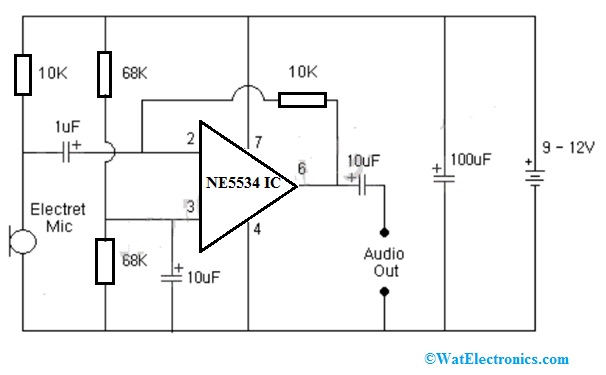 聽 聽 聽 聽 聽 聽 聽 聽 聽 聽 聽 聽 聽 聽 聽 聽 聽 聽 聽Low Noise Amplifier Circuit Diagram The main function of this low noise microphone pre-amplifier circuit is to amplify the weak audio signals. Once an audio source like the microphone has less sound range then this circuit is helpful in amplifying that low signal or weak signals & transmits that signal for further amplification. The above circuit can be designed with an IC instead of a transistor because this IC will provide a much better distortion filter. This low noise amplifier IC includes low noise, high unity-gain, low power consumption with short circuit protection, and low harmonic distortion. Here, the mic preamplifier specifications may change based on the mic used to capture the audio signals & the type of sound being recorded. The essential specifications to be considered within a pre-amplifier circuit are noise, distortion & gain. This circuit operates with a 9V to 12V battery. Here, Electret Mic generates audio signals that are transmitted to the input of IC. Here you can use any audio source instead of a microphone. This circuit鈥檚 overall voltage gain mainly depends on the resistors connected at the non-inverting terminal of the IC. The output signal which is generated from this IC can be transmitted through one more capacitor to filter out any noise. This circuit is very useful where low noise audio preamplifier is necessary like live music, cellphones, soundcard within laptops, and audio recording applications. Performance characteristics: The most important performance characteristic of an LNA is its noise figure (NF). This is defined as the ratio of output noise power to input power: NF = Pout / Pin where Pin is the total input power (sum of all signals) and Pout is the total output power (sum of all amplified signals). Thus, if you increase Pout by 10 dB while keeping Pin constant, NF will decrease by 10 dB. In practice, however, it’s difficult to keep Pin constant when amplifying weak signals; usually Pin has to be increased significantly in order to have a Low Noise figure. Types of Low Noise AmplifiersThere are different types of low noise amplifiers like the following. General Purpose LNA. GPS/GLONASS/COMPASS LNA. 4G/5G LNA. General Purpose LNAThese low noise amplifiers mainly include SiGe LNA & Wideband LNA product families. SiGe-type LNAs are optimized for various supply currents. They offer low noise figures & absolute stability for Wideband & MMIC driver amplifiers LNA designs. Their optimized internal transistor cell arrangement leads to the best noise figures & power gains at high frequencies. Wideband LNA design offers a variety of high-performance BFP products. These products utilize silicon germanium carbon bipolar technology for wireless applications. MMIC driver amplifiers use the Darlington configuration that offers a single package to RF designers. 4G/5G LNAThese low noise amplifiers are very important when it comes to communication systems as well as future technologies. By including a low noise amplifier to the antenna, then the signal can be improved without adding extra surplus noise to the system. The main benefits of using these low noise amplifiers are; high linearity, Ultra-low noise figure & low current consumption that improves the signal sensitivity, enhances data transfer rate, increases system integration & power consumption can be reduced. GNSS LNAsGNSS low noise amplifiers need a low or ultra-low noise RF amplifier and high linearity to improve the sensitivity of the receiver for best localization even in low battery or bad conditions. At present, most of smartphones have navigation applications, which impose even greater demands on size, linearity & power consumption as compared to stand-alone PNDs (personal navigation devices). These amplifiers improve signal sensitivity with very low current consumption and a wide range of voltage supply. How to design a Low noise amplifier ? A low noise amplifier can be designed using either a negative feedback topology or one without any feedback. The former approach is more commonly used because it can provide better performance when compared to an equivalent amplifier without feedback. What is the purpose of a low noise amplifier? . To increase the signal-to-noise ratio . To increase the gain of an amplifier . To remove unwanted noise from an electromagnetic wave . To attenuate the input of an amplifier What is the difference between noise and interference? Noise is unwanted signal that can interfere with the operation of a circuit. It is usually caused by thermal agitation, voltage fluctuations, or other electrical effects. Interference is an unwanted signal that interferes with the operation of another circuit. Please refer to this link to know more about DC Amplifier MCQs,聽 Low Noise Amplifier MCQs AdvantagesThe advantages of a low noise amplifier include the following. These are designed to reduce that extra noise. These electronic amplifiers are helpful in amplifying very low-strength signals. This amplifier is used once the SNR or signal-to-noise ratio is high & needs to be decreased by almost 50% while power is enhanced. These are commonly available in all receivers. While designing LNA, we use both active & passive feedback.The disadvantages of low noise amplifiers include the following. Low noise amplifiers are expensive. These are very sensitive to flicker noise & DC offsets. ApplicationsThe applications of low noise amplifiers include the following. These amplifiers are mainly designed to reduce the additional noise. Designers can reduce additional noise by selecting operating points, circuit topologies & low-noise components. Reducing extra noise should balance with the goals of other designs like impedance matching & power gain. These are mainly used in communications receivers like GPS receivers, cellular telephones, satellite communications & WiFi. Generally, an LNA is used in all receivers and the main function of this amplifier is to boost the received signal to a sufficient level so that it can be utilized for additional processing. LNA is a significant component that is usually located near the different detectors like GPS, Mobile phones, Radio, etc. These amplifiers amplify very weak signals & provide voltage levels appropriate for ADC. They are used in low amplitude sources like antennae & transducers. This amplifier can be used as an intermediate-frequency or a high-frequency preamplifier for different kinds of amplifying circuits & radio receivers for high-sensitivity electronic detection apparatus.Please refer to this link to know more about Parabolic Reflector Antenna, Class D Amplifier. Thus, this is all about an overview of a low noise amplifier or LNA. For the best working of these amplifiers, high gain and low noise figures are the main requirements. The efficiency of this amplifier can be determined by analyzing different parameters like noise figure, gain, stability, & linearity within the circuit. Here is a question for you, what is PA? Filed Under: Electronics Tagged With: Amplifier |
【本文地址】